
Page 29 - 2021 - Q2 - Minerva in Focus
P. 29
Commercial Systems: Operation Principle:
• Mitsubishi Air Lubrication (MALS) In Partial Cavity Drag Reduction (PCDR), a recess or cavity is created on the hull bottom
• Winged Air Induction Pipe System that captures a volume of gas and creates a cavity of air between the hull and outer flow.
(WAIP) As shown in the illustration, a backward-facing step on the upstream end and a gently
• Samsung Heavy Industries SAVER downward-sloping closure on the downstream side normally form the recess that traps
System (SAVER Air) the gas, thus forming a ventilated partial cavity. Gas is injected continuously into the
• Silverstream System cavity to maintain it as some gas is lost due to entrainment at the cavity closure;
• Foreship Air Lubrication System
(Foreship ALS) Limitations:
• Cannot be retrofitted and requires hull modifications.
2. Air Layer Drag Reduction (ALDR) • Loses effectiveness in high waves and rough seas
Commercial Systems:
• Damen’s Air Chamber Energy Saving (ACES) System
OVERALL ADVANTAGES
Also known an air film or air cushion, ALDR • Drop in Shaft Power
has been the oldest approach among • Increase in Ship Speed
designers since the early stages of the air • Reduction in hull and propeller fouling: The condition of hull coatings from un-
lubrication concept. Fundamentally, this derwater surveys and inspection on docking of vessels fitted with the Air Lubrica-
method’s purpose is to insert a thin layer of tion suggests that the level of fouling is less than otherwise would be anticipated
air between the hull surface and the water.
Operation Principle: CONSIDERATIONS
When sufficient air is injected beneath a From a technical point of view, it seems that ALS efficiency is drastically reduced in ves-
horizontal plate, the injected air, in the sels with a high draught difference between laden and ballast conditions, thus making it
form of bubbles, will coalesce to form a more lucrative for vessel types such as cruise and RO-RO’s LNGCs, etc. It is also generally
continuous or nearly continuous layer of acknowledged that ALS Systems are adversely affected by bad weather conditions, and
air, which separates the solid surface from their efficiency is not a given during rough seas.
the water flow. As the injected air flux in- Moreover, one of the primary considerations regarding air lubrication systems is their
creases, the coalesced air layer covers a actual performance outside the laboratory, as there is a limited number of full-scale
larger wetted surface and subsequently performance tests.
results in a greater skin friction drag It should be noted that a combination of an air lubrication system with a shaft generator
reduction. could yield the maximum gains in net daily consumption savings. This derives from the
fact that the ALS energy demand will be covered from the main engine(s), which in most
Limitations: cases outperforms the generator engines in terms of efficiency.
• A considerable amount of pressur- To sum up, air lubrication systems is a technology that enhances energy efficiency in se-
ized air is required to maintain the lected applications. The increasing number of vessels currently under construction that
integrity of the air film. will be fitted with ALS will provide the industry with a better insight into this technology.
• Efficiency is reduced at higher
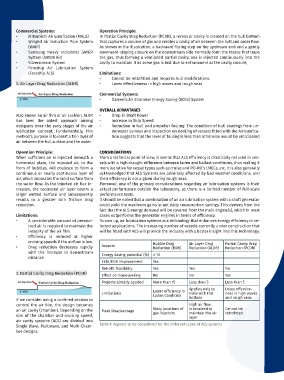
cruising speeds if the airflow is low. Bubble Drag Air Layer Drag Partial Cavity Drag
• Drag reduction decreases rapidly Aspects Reduction (BDR) Reduction (ALDR) Reduction (PCDR)
with the increase in downstream
Energy Saving potential (%) 4-10
distance
EEDI/EEXI Improvement Yes
Retrofit feasibility Yes Yes No
3. Partial Cavity Drag Reduction (PCDR)
Effect on maneuvering No No Yes
Projects already applied More than 15 Less than 5 Less than 5
Applies only to Loses effective-
Lower efficiency in
Limitations hulls with Flat ness in high waves
Laden Condition Bottom and rough seas
If we consider using a confined section to
control the air film, the design becomes High air flow
Many locations of is required to Cannot be
an air cavity (chamber). Depending on the Main Disadvantage
gas injectors maintain the air retrofitted
size of the chamber and cruising speed,
layer
air cavity systems (ACS) are divided into
Table 1: Aspects to be considered for the different types of ALS systems
Single Wave, Multiwave, and Multi-Cham-
ber designs.
27